Technical Specifications for FK-5-1-12 Clean Agent Total Room Gas Flooding System
1. GENERAL
1.1 INTENT OF SPECIFICATIONS
This specification outlines the requirements for a total flooding clean agent fire extinguishing system comprising ofUL Listed FK-5-1-12Clean AgentFire Protection Fluid.
All requirements outlined in this specification must be completed in their entirety. These requirements, which are in accordance with the items listed in Section 1.3, combined with good engineering practices shall be followed in order to produce a safe and effective clean agent fire extinguishing system.
1.2 GENERAL DESCRIPTION
The clean agent fire extinguishing system shall perform as outlined in the following sub-sections.
A. Achieve a 4.5% (v/v) extinguishing concentration for Class A (Surface Type Fires) hazards.
B. Achieve 5.85% (v/v) or greater, as required, extinguishing concentration for Class B (Flammable Liquids) hazards.
C. Achieve a 4.5% (v/v) extinguishing concentration for Class C (Energized Electrical Equipment) hazards.
D. Within 10 seconds, the clean agent fire extinguishing system shall discharge 95% of the required suppression agent mass to maximize extinguishing and minimize damage from fire and decomposition byproducts during extinguishing.
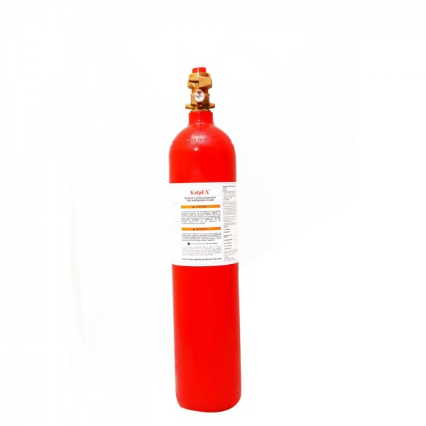
E. The clean agent fire extinguishing system shall consist of one or more Systems agent cylinders and related equipment. The cylinders may be either connected to a discharge pipe arrangement separately or connected to a common manifold and discharge pipe arrangement. The agent cylinders shall be filled with FK-5-1-12 fluidand super pressurized with nitrogen to 42 Bar at 21°C. The Cylinders shall be Seamless type and the cylinder Valve shall be PESO, VDS Approved with a safety burst disc pressure of 78 Bar and shall conforming to IS: 7285 standards. The Cylinder shall be filled in PESO Approved Filling Station. Letter of OEM Authorization is compulsory for supply of Items.
1.3 CODES AND COMPLIANCE
A. The design, installation, testing and maintenance of the clean agent fire extinguishing system, shall be in accordance with the following codes, standards and regulatory bodies:
1. NFPA 2001: Standard for Clean Agent Fire Extinguishing Systems
2. UL2166: Standard for Halocarbon Clean Agent Extinguishing SystemUnits
3. ANSI B1.20.1: Standard for pipe threads, General Purpose
4. NFPA 70: National Electrical Code (NEC)
5. NFPA 72: National Fire Alarm Code
6. FM: Factory Mutual Approval Guide
7. VDS Approved Parts
8. PESO Approved cylinder and valve
9. Gas Cylinder Rule, 2016
10. Requirements of the Local Authorities Having Jurisdiction (AHJ)
11. National Building Code of India 2016.
B. The manufacturer shall meet ISO 9001, ISO 14001 and ISO 45001 requirements for manufacturing of firefighting equipment’s and accessories.
C. All components of the clean agent fire extinguishing system shall be the products of the same manufacturer or listed by that manufacturer as compatible with those devices, components and equipment.
1.4 SYSTEM DESIGN CRITERIA
A. A total flooding clean agent fire extinguishing system, employing FK-5-1-12 fluid, shall be installed to meet a minimum design concentration mentioned as per NFPA 2001 (Latest Edition) in all designated spaces to be protected.
B. Systems capabilities:42 Bar maximum calculated working pressure and45 Barmaximum allowed system pressure.
1.5 QUALIFICATIONS
A. Contractor
1. The distributor shall be trained by the manufacturer to calculate/design, install, test and maintain the clean agent fire extinguishing system employing FK-5-1-12 fluid and shall be able to produce a certificate stating such on request.
1.6 WARRANTY
A. Components provided by the manufacturer shall carry a warranty of twelve (12) months from date of sale
1.7 QUALIFIED CALCULATION
A qualified system calculation shall be done as per NFPA 2001 Guidelines and it must be provided demonstration the capability to provide FK-5-1-12 for each hazard area.
1.8 SUBMITTALS
A. The AHJ will review all submittals for conformance to the drawings and specifications. The contractor shall be required to resubmit any materials, with appropriate modifications, that are found to be in non-conformance with the requirements of the drawings and these specifications after review by the AHJ. Approval of the submittals by the AHJ shall not relieve the Manufacturer/ Contractor of their responsibility to meet the requirements of the drawings and specifications.
B. Engineered Design Drawings: The Manufacturer/ Contractor shall provide all required documents that shall include the following details:
1. The factory-authorized OEM’s Systems Distributor shall provide all required installation drawings as per NFPA 2001.
C. Flow Calculation Reports
1. The distributor shall provide the following information in the flow calculation report.
i. Customer information and project data
ii. Hazard information. At a minimum, hazard information shall include minimum design concentration, minimum enclosure ambient temperature, minimum agent required and volume of enclosures, and identify discharge nozzles by quantity and style.
iii. Cylinder information. At a minimum, cylinder information shall include cylinder capacity, agent fill amount per cylinder and quantity of cylinders.
iv. Pipe network information. At a minimum, pipe network information shall include pipe type, pipe diameter, pipe length, change in elevation, pipe equivalent length and any added accessory equivalent length. In addition, the following nozzle information shall be provided; number of nozzles and identification of enclosure location, flow rate of associated nozzle, nozzle nominal pipe size, nozzle type and nozzle orifice area.
v. Pipes and pipe fittings. At a minimum, pipe and fitting summary shall include a detailed list of pipe by schedule, nominal diameter and length, and fittings, by Class Rating, nominal diameter and quantity.
D. Commissioning Equipment List: The distributor shall provide a commissioning equipment list for each installed clean agent fire extinguishing system. The equipment list shall identify all installed equipment and configurations.
E. Test Plan
1. The distributor shall submit a test plan that describes how the system equipment shall be tested. This shall include a step-by-step description of all tests and shall indicate type and location of test apparatus to be used. At a minimum, the tests to be conducted shall be as per NFPA 2001 and any additional supplemental tests required by the AHJ. Tests shall not be scheduled nor conducted until the engineer of record approves the test plan.
F. Installation Drawings
1. Four (4) sets of installation drawings for each installed clean agent fire extinguishing system and one (1) set of the calculation report, owner’s manual and product data sheets shall be submitted to the end-user/owner.
2. Upon completion of installation and commissioning acceptance, two (2) sets of “As-Built” installation drawings and One (1) set of the calculation report for each installed clean agent fire extinguishing system shall be given to the owner/end-user for use and reference.
G. Operation and Maintenance Manuals
1. Two (2) copies of the OEM Systems Design, Installation, Operation and Maintenance Manual for the clean agent fire extinguishing system employing FK-5-1-12 fluid shall be submitted after complete installation.
2. SUPPRESSION SYSTEM REQUIREMENTS
2.1 GENERAL
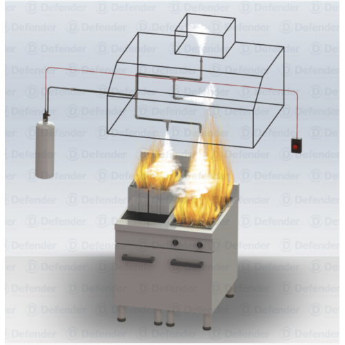
A. The clean agent fire extinguishing system shall consist of FK-5-1-12fluid, agent storage container(s),OEM actuation hardware and OEM discharge nozzle(s) attached to a pipe network.
B. The system shall be operated automatically and manually, and shall comprise the following equipment: -
1. Control panel with built-in maintenance free battery.
2. Interface with Smoke / Heat detectors.
3. Audible warning - alarm bells and hooters.
4. Visible warning - flashing and warning signs.
5. Manual release units.
6. Discharge nozzle and pipework
7. Time delay unit.
8. Associated equipment and accessories.
C. Abort stations shall be provided at each exit of the protected area and shall, when operated, shall interrupt the discharge of clean agent.
2.2 SYSTEM PERFORMANCE
A. System Discharge
1. The discharge time required to achieve 95% of the minimum design concentration for flame extinguishment shall not exceed 10 seconds.
B. Duration of Protection
1. 85% of the minimum design concentration shall be maintained for 10-minutes or a sufficiently longer period of time to allow effective emergency action by trained personnel. A level 1 certification in room integrity testing, provided by a manufacturer of room integrity testing equipment and/or recognized by OEM Systems is required.
C. Minimum System Design Limits
2.3 CLEAN AGENT STORAGE AND DISTRIBUTION
a) Each system shall have its own supply of clean agent.
b) Systems shall be designed in accordance with the manufacturer’s/NFPA 2001 guidelines.
c) Each supply shall be located within the hazard area, or as near as possible to reduce the amount of pipe and fittings required to install the system.
d) The clean agent shall be stored in seamless Cylinder Assemblies having CCOE / PESO approval and as per IS: 7285 standards.
e) Valve shall be constructed of forged brass and operate by means of pressure differential. Valve shall be constructed as to not require rebuild after discharge, Valve shall allow for means to pressurize cylinder without need for valve operation. The Valve shall be VDS approved and PESO approved.
f) The primary cylinder assembly(s) shall be actuated by a resettable electric actuator or
by pneumatic means from a pilot cylinder. Non-re-settable or explosive devices shall not be permitted.
g) The cylinders shall be mounted using wall racks on solid walls. The cylinders and racks shall be arranged to allow a service aisle for cylinder removal and cylinder weighing.
h) Each cylinder assembly shall have a contact pressure gauge with a low-pressure switch to provide visual and electrical supervision of the cylinder pressure. The low-pressure switch shall be wired to the control panel to provide an audible and visual supervisory condition signal in the event the cylinder pressure drops below 10% working pressure. The pressure gauge shall be color coded to provide an easy, visual indication of cylinder pressure.
i) Each cylinder assembly shall have a pressure relief provision that automatically operates before the internal pressure exceeds 78 bar.
j) When more than one cylinder is connected to a common manifold, a check valve with adaptor shall be provided with each cylinder.
k) Discharge nozzles shall be provided within the manufacturer’s guidelines to distribute the clean agent fluid throughout the protected spaces. The nozzles shall be designed to provide proper agent quantity and distribution. Nozzles shall be available in 1/2 inch through 2-inch pipe sizes. Each size shall be available in 180° and 360º distribution patterns.
• Nozzles shall be permanently marked as to part number and orifice diameter.
• Nozzles shall be of the type utilizing internal orifice plates.
• Nozzles should be listed and/or approved to be used in the upright or pendant position.
• Ceiling plates can be used with the nozzles to conceal pipe entry holes through ceiling tiles.
l) Distribution piping, and fittings, shall be installed in accordance with the manufacturer’s requirements, NFPA 2001 and approved piping standards and guidelines. All distribution piping shall be installed by qualified individuals using accepted practices and quality procedures. All piping shall be adequately supported and anchored at all directional changes and nozzle locations. The piping shall be laid out to give maximum flow and to avoid possible mechanical, chemical or other damage. Installation shall follow drawings as closely as possible. System designer must be consulted for anything other than minor deviations in pipe routing.
• CS pipe shall be either ASTM A53 seamless or ASTM A-106, Grade B -Schedule 40, Schedule 80(Manifold. ordinary cast-iron pipe, aluminum pipe, or non-metallic pipe shall not be used. Stainless steel pipe shall be 304, 316, 304L, or 31 6L for threaded connections or 304L or 31 6L for welded connections.
• Threaded/ Welded fittings must comply with NFPA 2001 and ASTM A234 WPW # 3000-pound fittings shall be used.
• Grooved fittings and couplings must comply with NFPA 2001. Piping shall be rolled or cut grooved in accordance with the fitting or coupling manufacturer's guidelines.
• Gaskets must be compatible with clean agent fluid (typically EPDM having a temperature range of -30°F to 230°F [-34°C to 110°C]). Gasket lubricant must be in accordance with manufacturer's specifications.
• Reductions in pipe sizes may be accomplished using threaded or grooved concentric reducing fittings, steel or stainless-steel concentric swage fittings, or steel or stainless- steel reducing bushings. All such fittings must comply with NFPA 2001. Pipe reductions can be made using machined or forged steel hex bushings. Malleable and/or cast-iron bushings are NOT to be used.
• All piping shall be reamed, blown clear and swabbed with suitable solvents to remove burrs, mill varnish and cutting oils before assembly.
• All male threads on pipe shall be tapped with approved Teflon tape.
• Piping shall be pneumatically tested in a closed circuit for a period of 10 minutes at 40 psi (2.76 bar) per the latest edition of NFPA 2001. At the end of 10 minutes, the pressure drop shall not exceed 20 percent of the test pressure. The pressure test shall be permitted to be omitted if the total piping contains no more than one change in direction fitting between the storage container and the discharge nozzle, and where all piping is physically tested for tightness.
4) MANUAL RELEASE (MECHANICAL)
Mechanical Manual Release shall be made available in the event all battery back-up and commercial power is lost. Mechanical Manual Release shall be installed a top the electric actuator. Consideration should be given for convenience of operation and egress from the hazard area(s).
5) Control Panel
(a) The control unit shall include the following: -
• “Mains On” indication.
• “System Fault” indications.
• Separate “Zone Fire / Fault” indications.
• Indication of “Gas Discharge”;
• Power unit;
• Battery and charger; and
• Switches for bell silencing, testing and resetting of the system.
(b) The unit shall be suitable for use on single phase supply voltage as specified in the General and Specifications and shall automatically maintain the 24 V batteries in a state approximate to full charge and at the same time compensate for the standing load.
(c) Batteries shall be of maintenance free sealed Ni-Cd type requiring no maintenance throughout the normal life of the battery and shall be of capacity capable of maintaining the system in normal working condition for at least 24 hours without recharging and subsequently to operate in the "alarm" condition continuously for at least one hour.
(d) Battery Charger and Batteries
The control unit shall include the following: -
• Trickle and boost charger assembly.
• One incoming double pole control fuse; and
• Maintenance free batteries
2.3 ACTUATION HARDWARE
A. The agent containers shall be actuated in accordance with the applicable design manual.
B. Electromagnetic, manual & Pneumatic release devices shall be VDS Approved and shall not require scheduled periodic replacement.
C. The gas release panel shall conform to IS: 2189 with the interfacing electromagnetic release device.
3. EXECUTION
3.1 CLEAN AGENT FIRE EXTINGUISHING SYSTEM INSTALLATION
A. The system shall be supplied and installed by a factory-authorized, OEM Systems Distributor. The Distributor shall be trained and certified by OEM Systems to design, install and maintain the OEM fire suppression system. The distributor shall install the system in accordance with the manufacturer’s design, installation, operation and maintenance manual.
3.2 ELECTRICAL SYSTEM INSTALLATION
A. All electrical enclosures, raceways, and conduits shall be provided and installed in accordance with applicable codes and intended use, and shall contain only those electrical circuits associated with the fire-detection and control system. No circuit or circuits that are unrelated to the fire alarm or suppression system shall be routed through the enclosures, raceways, and conduits dedicated to the fire alarm or suppression system.
B. Splicing of circuits shall be kept to a minimum, and is only permitted in an electrical box suitable for the purpose. Appropriate hardware shall be used to make the wire splices. Wires that are spliced together shall have the same color insulation.
C. White colored wire shall be used exclusively for the identification of the neutral conductor of an alternating-current circuit. Green colored wire shall be used exclusively for the identification of the earth-ground conductor of an AC or DC circuit. Appropriate color-coding shall be utilized for all other field wiring.
D. All electrical circuits shall be numerically tagged with suitable markings at each terminal point. All circuits shall correspond with the installation draw.
3.3 ROUTINE MAINTENANCE
A. Routine maintenance on equipment shall be performed as recommended by the manufacturer’s installation, operation and maintenance manual. At a minimum the routine maintenance will include the following by a certified OEM Systems Distributor:
1. Visual Check of Pipe network and distribution nozzles per the operation and maintenance manual.
2. Weight and pressure of the OEM Engineered System containers/cylinders per the operation and maintenance manual.
3. Inspect all cylinders and equipment for damage as per the operation and maintenance manual.
4. Routine maintenance on the suppression system as a whole shall be performed as recommended by NFPA 2001, latest edition.
4 APPROVALS/CERTIFICATIONS SHALL BE REQUIRED :
) Authorization/distributorship Letter from OEM of system.
b) VDS approved parts
c) Valve shall be PESO approved.
d) Cylinder shall be PESO approved
e) PESO approved filling station.
f) Computer Generated Flow calculation.

