FIRESUPPRESSIONSYSTEM
(with Heat Detection Tube)
1. General
This section includes provision of Automatic Linear Pneumatic Heat Detection Tube gas suppression system of approved clean gases agent having global warming potential (GWP) ≤ 1andcomplying NFPA-2001 (latest edition).
Letter of OEM authorization is compulsory for supply required by the contractor.
2. Standard & code
Following Indian / internationalstandard specifications,codesof practiceetcupdated shall applytotheequipmentandtheworkcoveredbythescopeofthiscontract.
| NFPA 2001 | Standard on clean agent fire extinguishing system |
| UL 521 | UL Standard for Heat Detectors for Fire Protective Sign alling Systems |
| LPS 1666 | Direct Low Pressure application for fixed fire suppression |
| GCR 2016 | Gas Cylinder Rules 2016 |
This scope of broadly covers the following:
i. Design and provide clean Agent AutomaticLinear Pneumatic Heat DetectionTubeFire Gas Suppressionsystem in a uniform concentration within electrical panel/ section(s) inaccordancewithNFPA2001 and system complying theLPS-1666 Standard.
ii. Provide sufficient amount of extinguishing agent HFC 227 ea, considering the following key points when computing volume to verify suitability and to establish design limitations:
Volume of hazard area.
Specific volume of Clean agent.
Discharge time and flow rates.
Design Concentration and design factors.
Detector/ discharge tubing placement in co-ordination with panel / equipment drawings
iii. The system shall be designed to enable a single container heat detection tube installation run to protect a maximum single volume of 2m3.
iv. Up to 4 Heat detection tube runs maybe connected to a single container where no single protected volume exceeds a 2m3 of volume.
v. The maximum heat detection tube length from the container outlet to the end of any single detection tube shall not exceed 10m.
vi. Provide all engineering design and materials for a complete agent suppressionsystemincludingstoragecylinderswithsteelbracket,extinguishingagent,detection tube, cylinder valve and associated accessories including but not limited to; adaptors,pressureswitch,tubefittingscomplete as required for successful & safe operationof thesystem.
vii. Provision of all necessary safety requirements such as - warning signs, discharge alarm etc as a partof the system.
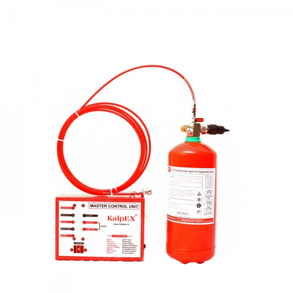
viii. Master control unit shall consist of hooter cum flasher, inbuilt 12 V battery pack(ofminimum 30 minutes back up), two NO & NC contact, charging circuit,extension of power supply from nearest power point, connection / inter-connection complete suitable for system activation.
ix. Thenecessarynomenclaturesuchaspressurizationlevel,agentvolume,gross /net weightofcylinder and filling date etcshallbeclearlymarkedoncylinder.
x. All doors and holes in the enclosed / equipment should be closed or sealed tomaintainthetightnessofenclosure.Therefore, executing agency has to coordinate with manufacturer of electrical panels for provision of holes to run the
tube and brackets for mounting the tube during panel fabrication. The entry of tube inside the panel shall be through suitable size of connectors.
xi. Contractor has to submit detailed drawings & gas calculations sheet based on NFPA 2001 (Latest Edition) & specifications for approval.
4. System Description
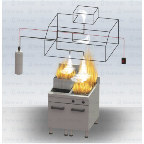
i) The detection tube shall be installed throughout the compartments of panel vizbusbar section, switchgear section, cable alleys and back of the panel section (if provided) as per system design requirement. Thelocationandspacingoftubeshallbeabovethehazard,to beprotected.
ii) The detection tube shall be fixed with PESO approved cylinder & valve. The valve shall be at top ofcylinder. The tube shall be pressurized with dry nitrogen to 15 Bar. In case of reach of pre-determined temperatureas specified in UL certification, the tube shall rupture at a point and gas shall bereleasedfromtubeovertheprotectedarea in electrical panel section (s)/ compartment inuniformpattern.
iii) The detection tube shall be capable of working even when contaminated with oil, dust, and debris as long as the contamination will allow the heat to pass through the tube.
i) The cylinder shall be equipped with brass valve, pressure gauge ( to monitor agent pressure) and isolation valve for maintenance purposes. The cylinder valve shall be with a safety burst disc of 28 Bar rupture Pressure.
iv) The Extinguishing Agent shall be stored in cylinder as liquefied compressed gas,superpressurizedwithdrynitrogenat(195-220)psi.
v) Pressureswitchshallhave necessaryindicationofdischargeofgas with NO & NCcontactfor interaction with Main Fire Alarm Panel / BMS / SCADAforcentralizedmonitoring. switch points 8 bars
vi) With the system activation, master control unit with hooter cum flasher shall generate audio visual alarm signal for electrical panel/ compartment is covered.
vii) System shall be so designed & provided that it does not affect the IP ratings of electrical panels.
5. System Components
i) PESO approved Cylinder of steel construction with standard red epoxy paintfinish. Cylinders shall be accompanied by original manufacturers test certificateconfirming thecontents ofthecylinder andfilled inPESOApproved plant.
ii) Each cylinder shall have pressure gauge and integrated low pressure switch to provide visualandelectricalsupervisionofthecylinderpressure.ThelowpressureswitchshallbewiredtotheAudioVisualAlarmtoprovideaudibleandvisualtroublealarminthe event of drop of pressure. The pressure gauge shall be color coded to provideaneasy,visualindicationofcylinderpressure.
iii) The cylinder shall be equipped withbrass valve, pressure gauge (to monitor agentpressure) and isolation valve for maintenance purposes.The cylinder valve shall be with a safety burst disc of 28 Bar rupture Pressure.
iv) Furnishaweldedsteelbracketwitheachcylinderassemblyforholdingthecylinders inasaddlewitha frontbracketpiecethatsecuresthecylinders.
v) Cylinder shall be provided with a certificate provided by the company who chargewith the gas mixture. The certificate shall be secured around the cylinder withchainfastener.
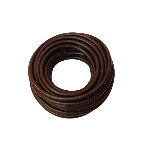
vi) The Detection Tube shall be ULapprovedred / black inColourandpressurizedaspersystemdesignrequirement.
vii) Theintegrated PressureSwitch (CE/UL/LPCB marked)shouldbeintegral part of valvehavingNO /NC contact.
viii) The control box enclosure shall be at least IP 54 rated from OEM of gas suppression system provider complying standard.The unit shall have LED indication for system Healthy, Mains Healthy and Gas Release. The unit shall also have signal silence button. Third Party test reports for IP and Functionality of the system to be submitted for approval complete as required.
6. Extinguishing Agentshall be UL and FM approved HFC 227ea in technology as applicable at the time of execution of work shall be acceptable with -
i) ExtinguishingagentshallbeULlisted/FMapproved.
ii) Global warming Potential should be less than equal to 1
iii) The clean agent shall be specified in NFPA 2001 having 99.9% purity and Certificate of conformity from OEM to be provided.
iv) TheextinguishingagentshouldbefilledinaPESOapprovedfillingstation.
7. Installation
i) Thesystemshallbeinstalledas per approved shop drawings.
ii) Theinstallation/finalconnectionsshallcarryoutindirectsupervisionofrepresentativeof Manufacturer/ specialized agency .
iii) Cylindershallbelocatedsothattheyarenotsubjectedtomechanical,chemicalorotherdamage.
iv) Allsystemcomponentsshallbecapableofwithstandingheatoffireandsevereweatherconditions.
v) DetectionTubetobeproperlysecured inside thepanelbyClips/Tieetc.
vi) TheDetectionTubeoutsidethepanel shouldbeprotectedinflexible conduit.
vii) Inspectioncertificateshouldbepastedoncylinderclearlymarkingnextduedateofinspection.
8. Testing & acceptance
Testing of the system shall be done at site by holding the Nitrogen Pressure at 14 Bar into the detection tube for 24hrs to check for any pressure leakage of the system. If there is no pressure leakageof the system then, the installed system is accepted as healthy and the isolation valve shall be opened.
9. Documentations
On award of work, contractor to prepare / submit three sets of following shop drawings & technical submittals of automatic Linear Pneumatic Heat Detection tube fire suppression system for approval of EIC / consultant and got approved by the Engineer-in-charge before commencement of work / procurement of any items.
a) General arrangement (GA) drawing of each system shall be supported with:
- Shop drawings shall clearly show routing of tube inside the panel as well as in equipment compartments as per system design requirements, location&fixingarrangementofcylinder& its systemcomponents, cut out details in panels etc
- Control & Schematic Diagram
- Bill of Materials/quantities indicating makes, technical specs, quantity etc.
- Data sheets (where applicable)
- Control logic and write up (where applicable)
- Technical leaflets / specifications.
b) Design/ selection sheet of Automatic Linear Pneumatic Heat Detection Tube gas suppression system referring relevant standard to be submitted for approval of EIC. Final two sets on approval shop drawings shall also be submitted for manufacture of panel as well as execution of the works at site.
10.0 Completion Plan
On completion of work, the contractor shall submit 4 sets of following documents along with soft copy of as built drawings. The drawings shall be Computer aided design drawings (CADD).
• General Arrangement Layout drawings with dimensions, plans, sections, etc.
• Single Line Diagram
• Control & Schematic Diagram
• Bill of Materials/quantities indicating makes, technical specs, quantity etc.
• Data sheets
• Control logic (where applicable)
• Details of Inventory
• Equipment name plate details
• Installation & Maintenance Manuals
• Test certificates (Factory tests, Site tests)
• Guarantee/Warranty certificates (where applicable)
*********

